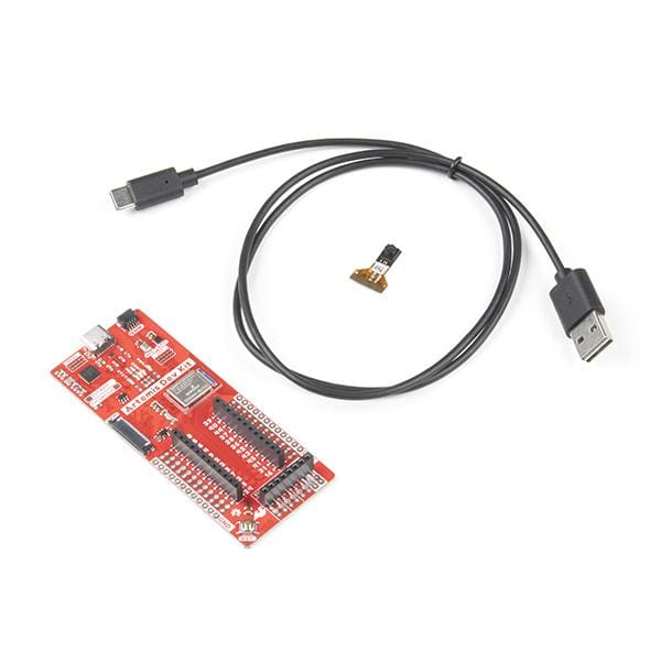
Artemis Development Kit with Camera
£34.19 ex VAT
The SparkFun Artemis Development Kit is the latest board to be released around the SparkFun Artemis Module and it allows access to more software development features than previous Artemis based boards. This Kit includes the SparkFun Artemis DK board as well as the accessories (Himax camera & USB-C cable) needed to get started right away. Recommended software used to program the Artemis DK are the Arduino IDE, Arm® Mbed™ OS (Studio and CLI), and AmbiqSDK. An updated USB interface (MKL26Z128VFM4 Arm® Cortex®-M0+ MCU, from NXP) allows the Artemis Dev Kit to act as:
- Mass Storage Device (MSD): Used to provide drag and drop programming to the Artemis Module.
- Human Interface Device (HID): Used for the debugging interface to the Artemis Module.
- Communication Port (COM): Used to provide a serial communication UART between the Artemis and the USB connection (PC).
The Artemis Module provides a Cortex®-M4F with BLE 5.0 running at 48MHz with an available 96MHz turbo mode and power as low as 6uA per MHz (less than 5mW). The SparkFun Artemis Module is fully FCC/IC/CE certified with 1M flash and 384k RAM you'll have plenty of room for your code.
The flexibility of the Artemis module starts with our Arduino core. You can program and use the Artemis module just like you would an Uno or any other Arduino. Additional functionality stems from the ability of the Artemis Devkit to run RTOS such as the Arm Mbed OS, or the AmbiqSDK.
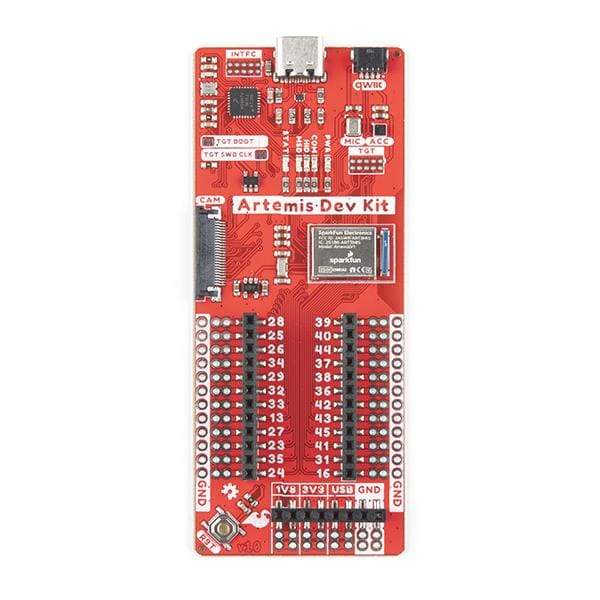
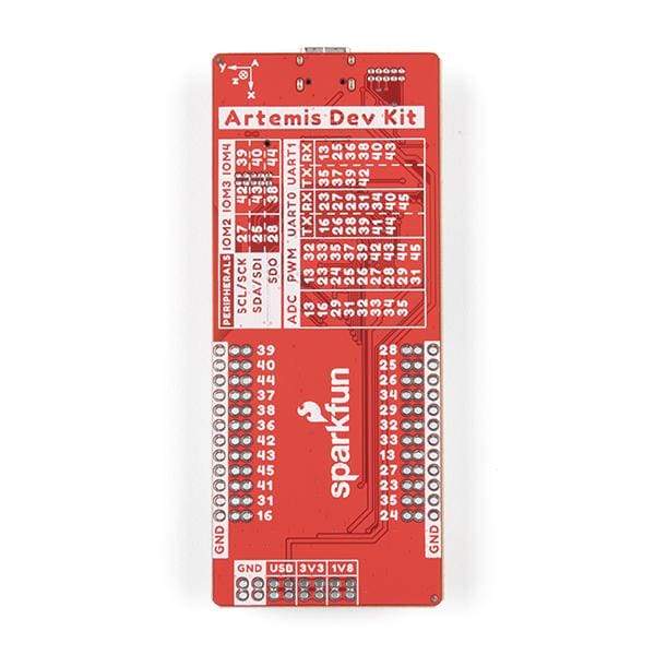
Attached to the "Qwiic" I2C bus, we've added a LIS2DH12TR MEMS accelerometer (for things like gesture recognition), a digital MEMS microphone, and an edge camera connector for the Himax CMOS imaging camera to experiment with always-on voice commands, and image recognition with TensorFlow and machine learning. All of the Artemis Development Kit pins are broken out to 0.1" spaced female headers (i.e. connectors). There are also two rows of breakout pins with 0.1" pitch spacing for headers; and a 0.08" pitch spacing to clip on IC-hooks, used by most logic analyzers. Additionally, the Silk on the back of the Artemis DK acts as a chart to show pins by functionality (peripherals, ADC, PWM, UART0, & UART1) and acts as an aid while developing software. The board is powered & programmed via USB-C, and includes a Qwiic connector to make I2C easy and is fully compatible with SparkFun's Arduino core to be programmed under the Arduino IDE.
Artemis Dev Kit
- Compatible with Arduino, Mbed™ OS, and AmbiqSDK Development Programs
- Power:
- 5V Provided Through the USB-C Connector
- 1.8V, 3.3V, and 5V Available on Power Header
- Interface Chip (MKL26Z128VFM4 ARM® Cortex®-M0+ MCU):
- Drag and Drop Programming
- SWD Interface
- JTAG Programming PTH
- Artemis Module:
- Apollo3 ARM® Cortex®-M4F MCU
- BLE 5.0 with FCC Certification
- 24 Breakout I/O Pins
- Eight 14-bit ADC Pins
- Eighteen 16-bit PWM Pins
- Two Independent UART Ports
- Three Peripheral I2C/SPI Buses
- JTAG Programming PTH
- Sensors:
- 3-axis Accelerometer (LIS2DH12)
- PDM Microphone (SPH0641LM4H-1)
- Camera Connector (for the Himax HM01B0 Camera)
- Qwiic Connector On Primary I2C Bus
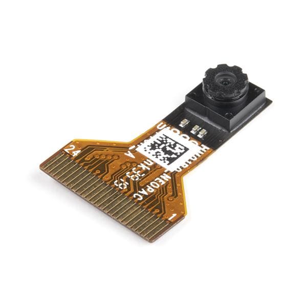
Himax HM01B0 Camera
Image Sensor
- Ultra Low Power Image Sensor (ULPIS) designed for Always On vision devices and applications
- High sensitivity 3.6µ BrightSenseTM pixel technology
- 320 x 320 active pixel resolution with support for QVGA window, vertical flip and horizontal mirror readout
- Programmable black level calibration target, frame size, frame rate, exposure, analogue gain (up to 8x) and digital gain (up to 4x)
- Automatic exposure and gain control loop with support for 50 / 60Hz flicker avoidance
- Flexible 1bit, 4bit and 8bit video data interface with video frame and line sync
- Motion Detection circuit with programmable ROI and detection threshold with digital output to serve as an interrupt
- On-chip self oscillator
- I2C 2-wire serial interface for register access
- High CRA for low profile module design
Sensor Parameters
- Active Pixel Array 320 x 320
- Pixel Size 3.6 µm x 3.6 µm
- Full Image Area 1152 µm x 1152 µm
- Diagonal (Optical Format) 1.63 mm (1/11″)
- Colour Filter Array Monochrome and Bayer
- Scan Mode: Progressive
- Shutter Type: Electronic Rolling Shutter
- Frame Rate MAX 51 fps @ 320 x 320, 60 fps @ 320 x 240 (QVGA)
- CRA (maximum) 30º
Sensor Specifications
- Supply Voltage: Analog - 2.8 V, Digital - 1.5V (Internal LDO: 1.5V – 2.8V), I/O - 1.5 – 2.8V
- Input Reference Clock: 3 – 50 MHz
- Serial Interface (I2C): 2-wire, 400 KHz max.
- Video Data Interface: 1b, 4b, 8b with frame / line SYNC
- Output Clock Rate MAX: 50 MHz for 1bit, 12.5 MHz for 4bit, 6.25 MHz for 8bit
- Est. Power Consumption (include IO with 5pF load):
- QVGA 60FPS (Typical) <4 mW
- QVGA 30FPS (Typical) <2 mW
Eagle Files
Board Dimensions
Hookup Guide
Software Guides
- Artemis Development with the Arduino IDE/a>
- Artemis Development with Arm® Mbed™ OS (Beta)
- Artemis Development with the AmbiqSDK
Hardware Component Information:
- Artemis Module
- Interface Chip
- Himax Camera (HM01B0) Datasheet
- PDM Microphone (SPH0641LM4H-1) Datasheet
- Accelerometer (LIS2DH12) Datasheet
- SparkFun Qwiic Connect System
GitHub Repository for Apollo3 Board Support Packages (BSP)
DAPLink Bootloader:kl26z_artemis_dk_if.bin
DAPLink Interface Firmware:kl26z_bl.bin
Development Platforms for Artemis Module:
- SparkFun Ambiq Apollo3 Arduino Core
- .json file needed for the SparkFun Ambiq Apollo3 Arduino Core: https://raw.githubusercontent.com/sparkfun/Arduino_Apollo3/master/package_sparkfun_apollo3_index.json
- Mbed™ OS
- AmbiqSDK/a>
- pyOCD