The USB Type-C connector is intended to supersede a wide range of existing USB connectors. It is reversible and can serve in both USB host and USB device roles, allowing either end of a cable to be plugged into a receptacle with either side up, and it can support negotiation of increased power (up to 20 V and 5 A) and alternate uses of the USB interface wires.
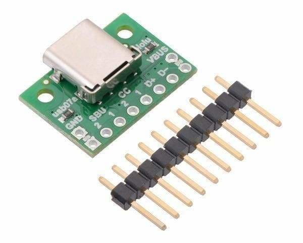
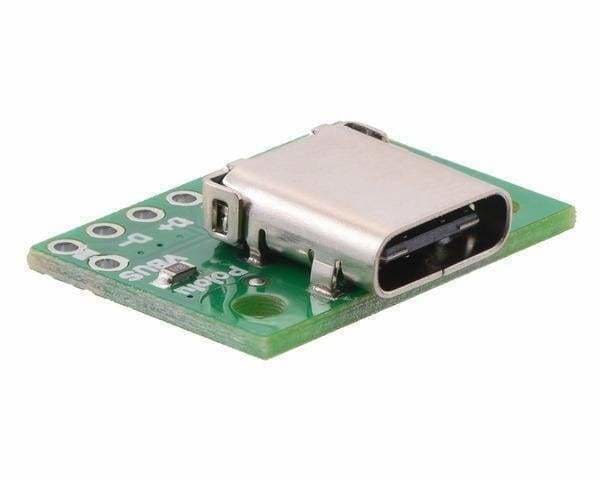
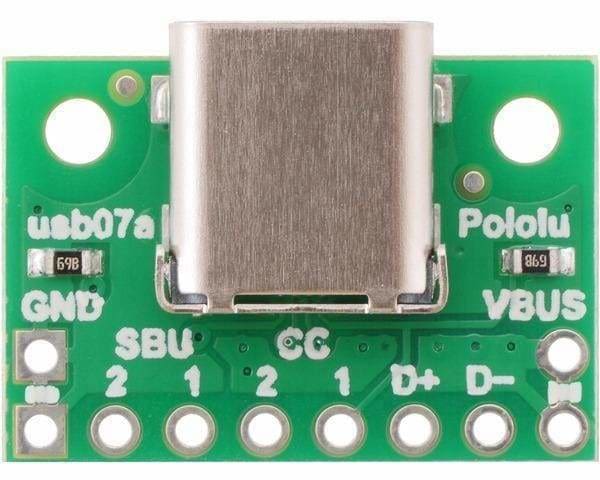
The USB-C connector’s 24 tightly-spaced pins make it difficult to use in a hobby project or prototype design. This breakout board helps by providing access to the connector’s pins for power (VBUS and GND), USB 2.0 differential data (D+ and D−), Configuration Channel (CC), and Sideband Use (SBU).
Please Note:
- This board does not expose the Type-C connector’s USB 3.1 SuperSpeed differential pairs (TX and RX signals)
- It only supports USB 2.0 Low-Speed, Full-Speed, and High-Speed communication.
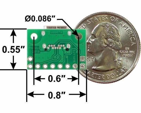
This tiny unit measures only 0.8″ × 0.55″ (0.8″ × 0.6″ including its USB Type-C connector) and has two 0.086″ diameter mounting holes for #2 or M2 screws.
Using the breakout - Configuration and auxiliary pins
A Type-C receptacle can either provide power as a “Source” or consume power as a “Sink”; this usually corresponds to whether the port is a USB host (Downstream Facing Port, or DFP) or USB device (Upstream Facing Port, or UFP). The Configuration Channel, or CC, pins are used to determine the role of a port when it is connected.
This carrier board pulls the CC1 and CC2 pins to GND through 5.11 kΩ termination resistors, making the port a Sink and a UFP by default and allowing it to be a straightforward replacement for a Type-B, Mini-B, or Micro-B port on a USB device. If you want the port to serve as a Source instead, or if you want to perform a more advanced configuration like USB Power Delivery negotiation, you can disconnect or remove the onboard resistors and make your own connections to the CC pins exposed by the board.
The Sideband Use, or SBU, pins are not used by the USB protocol. Instead, they are available for use after the USB interface has been configured (via the CC pins) to operate in Alternate Mode, which allows it to be repurposed for other protocols and applications.