
Welcome to a new video & blog series where we're going to go through the basics on getting started with an Arduino based development board. In this part, we'll be taking a look at the Arduino Uno board and the components it has on it. Having a look around in the Arduino programming software at some of the buttons and menus that you'll be frequently using. Then we're going to look at the structure of some example code and program the board for the first time.
You can use the quicklinks below to jump to the different parts of this post.
Arduino Uno Breakdown
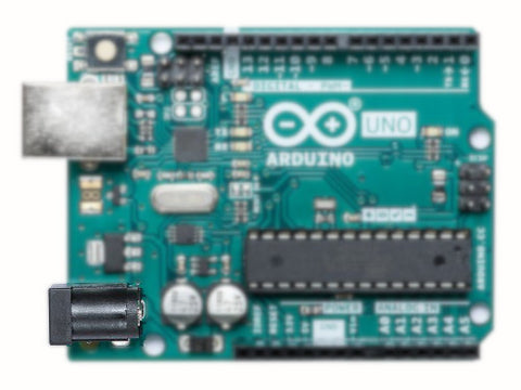
The Arduino Uno is an ideal development board for education or beginners looking to get started in electronic, it's the board we suggest to anyone that's not had any previous experience with an Arduino board. Lets start with a breakdown of the major parts/components on the board and what they're used for.
Microcontroller:
This is the brain of the board, it's the component that processes the calculations and instructions you program it to do.

LEDs:
The Uno four LEDs that all have different uses. There is a power LED on the right of the board which should always be lit when the board is connected to power via the barrel jack or USB ports. The TX & RX LEDs are used to indicate activity on the serial pins. You'll often see these flashes when you program the board.The last LED labelled L is the one which you can control and use when we program the board, it's used in the Blink example program which we'll be looking at later in this video and is referenced as PIN13 on the Uno.

Barrel Jack:
This 5.5mm barrel jack port is used to power the board externally, it accepts anywhere between 7V-12V.
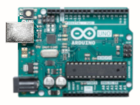
USB:
This USB A port is used to connect the Arduino board to a computer which enables you to use the Arduino IDE and program the board. As well as being used to program the board it can also be used to power the board at 5V.
Reset Button:
This push button causes the microcontroller to reset and restart the code/program stored in its memory. This is really useful when testing and troubleshooting code or circuits that use the board.

Pins:
There are 14 digital I/O pins, 6 of which are PWM (Pulse Width Modulation) pins and also 6 analogue inputs. These pin connectors are what you'll use to interface your Arduino with external circuitry such as sensors, displays, actuators and so much more.

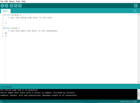
Arduino IDE Breakdown
This is the IDE we're going to go over some of the button and menus that you'll frequently be using and explain what they do.
First is the File menu, there is your standard New, Open and Save options.
The sketchbook option will show the local arduino projects on your computer.
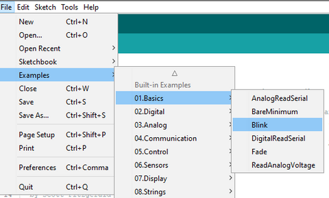
Examples is an important section as it will allow you to access built in examples as well as any from the libraries you install for specific sensors or other components
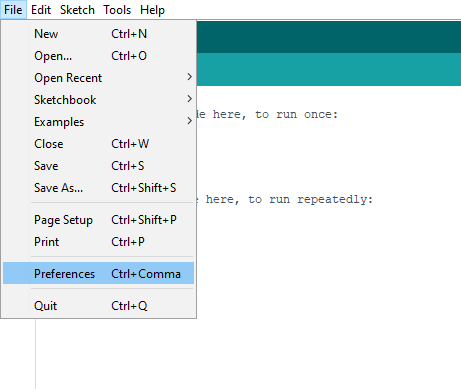
Another important section is the preferences option, in here you can change the settings for the software and also add URLs of additional board types.
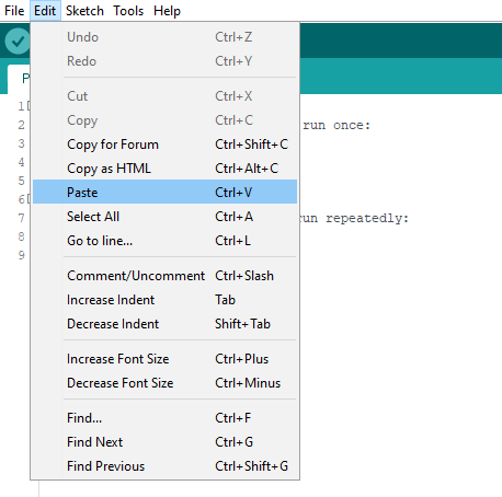
The edit menu has some standard functions such as copy and paste, comment/uncomment. You probably won't use this menu that much, but should still remember it's here.
Probably the most important menu is the Sketch menu.
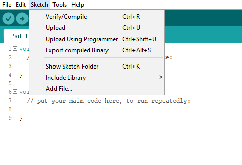
In here you can verify and compile your code which will tell you if there are any errors in it. You can upload the program to the board and you can also add libraries.In the include libraries menu you can add libraries using either a ZIP file or the library manager.
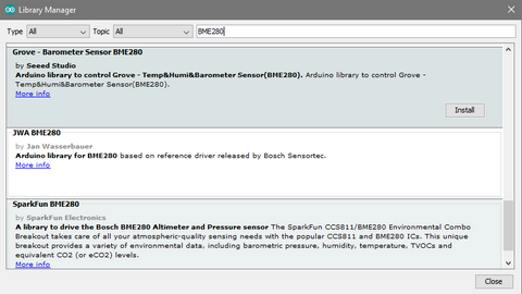
This is the library manager, in here you can search and install libraries for a huge range of components and other uses.For example if I'm using a BME280 sensor I can simply type it in and then install the library. Once installed there will usually be examples showing you how to use the functions and sensors the libraries are for.
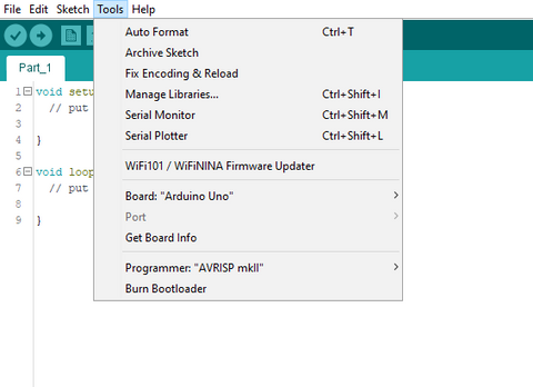
Another very important menu is the Tools menu, there's quite a few different options and tools in here that you'll use frequently.These will be the board submenu, in here you'll need to select the board you intend to program.
If the board is not in the list you can use the boards manager which operated in the same way as the library manager. Simply search for the board you want to use and install it.
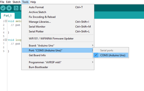
You'll also need to use the Port submenu frequently, in here you need to select the com post you currently have the Arduino board connected to. As you can see the Arduino I'm using is connected to COM Port 3.

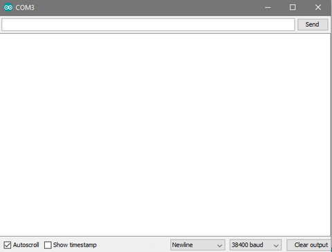
In the Tools Menu there is also the serial monitor and plotter. These are windows that can be used to display information from the board such as sensor reading, it's also a great way to communicate and interact with the board via a serial connection.
The only main parts of the IDE left are the code which we'll look at below and the buttons under the menus.
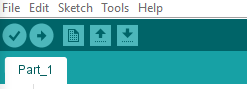
The first button, the tick, is to verify and compile the code. This does the same as the menu option in the sketch menu.
The next button is the upload button, this will push the compiled code to the boards memory. If you press upload without verifying the code, it will do this before uploading the code to the board.
The next button creates a new sketch and the last twp buttons are for saving and opening a sketch.
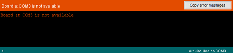
Any errors when compiling or uploading your code will be displayed in the error box down at the bottom of the software.
Example Code Breakdown
Now we've had a look at the IDEs menus and buttons. Let's look at some example code.
We're going to open an example by selecting File -> Examples and we'll be using the built-in example called Blink.
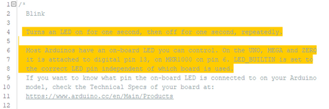
As you can see in this comment block, it gives a brief overview of what the example code will do. This code will flash the onboard LED on and off with a delay in the middle. This means no external components are required. Most example code will be well commented using a // or /* */, these comments should tell you what each line of code does
First we've got this void setup section. Typically here all the functions of the pins being used are defined. So this line of code is defining pin 13 (the built in LED) will be used as an output.
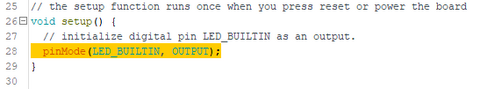
This section of code is run everytime the reset button is pressed or when power is first provided to the board.
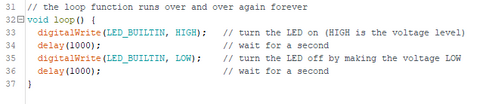
After the setup section we have this void loop which contains the code that will run continuously over and over and over while power is provided to the board.
There is a few different things going on here so we'll look at them in parts.
First is this digitalWrite function.A digitalWrite is used to change the state of a digital pin to either HIGH or LOW.The first part is the pin number and the second part is the state you want to change the pin to.As you can see in the comment this will turn the onboard LED ON.
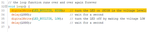
Next we have a delay. The delay function uses milliseconds, so here we've got 1000 milliseconds which is one second.So after the LED it turned on there will be a one second delay.

After that we've got another digitalwrite but this time we're setting the state to LOW which will turn the LED OFF.
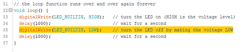
Then there is another one second delay after which the code will loop back to the first line in the void loop.So this section of code will turn the LED on, wait one second, turn the LED off, wait another second and then loop back to the beginning and turn it back on.
Programming the Arduino
The last thing we need to do is send this code to the Arduino board. Before we do that there are a couple of things we need to check. The first is that we have the correct board selected. So we're going to go into the Tools menu and check that we have the correct board selected in the board submenu. Then in the Port submenu we need to check we have the correct com port selected for our board. As you can see my Uno is connected to COM Port 3.
You can either click verify and then select upload after or you can press upload which will verify the code before uploading anyway. So if you click upload, you'll see down near the black box at the bottom that the sketch is being compiled and then it's uploaded to the board.
Now if you look at your Arduino you should see the onboard LED flashing on and off with a delay exactly as the code defines.
Thanks for reading, look out part two where we'll be using the status of a button to control an LED, This will involve digital input and outputs, variables and an if else statement.