
Hello and welcome to the second episode in our series on getting started with an Arduino development board. In this blog we'll be writing our first program which will turn an LED on and off depending on the status of a button. To achieve this we'll be using digital inputs, outputs, some variables and an if statement in our code. We'll take a look at how each of these work and how to use them.
You can use the quicklinks below to jump to the different parts of this post.
Arduino boards can be used to their full potential when connected to other electronic components and circuits. In this blog we'll be using a few additional components with the board but don't worry we'll walk you through what you need and how they're all connected.
We'll be using:
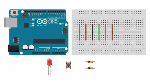
These components will be in two mini circuits, one will be for detecting the button press and the other will be used to light the LED.
Before we get to making these two circuits we're going to set up our breadboard. They're an amazing prototyping tool but you need to understand how they work. There are usually two power rails that run horizontally across the top and bottom of the breadboard.
Each of these rails is interconnected meaning you can connect a signal such as 5V to the leftmost pin and also connect to it using the rightmost pin. The main body of a breadboard is made up of a number of vertical rows, each of these vertical rows or connections are connected.
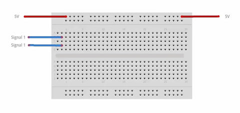
If there is a central gap in the breadboard then it's important to note that the top and bottom halves act separately. This allows you to mount things like buttons or IC chips.
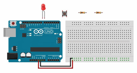
We can set up our breadboard by connecting the power from the Arduino to the power rails on the breadboard. You can do this by connecting the 5V pin from the Arduino to one of the horizontal rails at the top of most breadboards using a Jumper wire and then connect the GND ground pin to a different one. These horizontal rails are connected meaning we can connect to 5V at anyone of the other pins in that row. This isn't essential but it's a good habit to get into as it will make your circuits neater and easier to understand.
Button Circuit
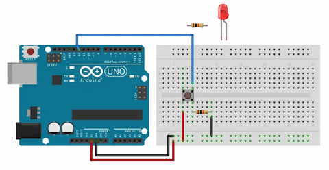
We'll be using the button with a resistor in a configuration often referred to as a pull-down resistor. This means that when the button is unpressed there is not a connection between the pins on the button making theoutput 0V (or LOW). When the button is pressed there is a complete connection and the 5V is dropped across the resistor making the output 5V (or HIGH).
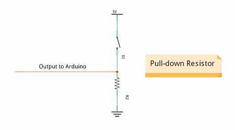
To create this circuit we'll need to connect one side of the button to the 5V rail and the other to GND via the pull-down resistor. Then we can use the pin on the button opposite where the resistor is connected as an input to the Arduino. You can connect it to any of the digital pins on the Arduino but you'll need to remember which pin number you've used for when we program the board, in this video we'll be using pin 12 as our button input.
LED Circuit
To create the LED circuit we'll be using a standard through hole LED and a current limiting resistor. It's important to use current limiting resistors with LEDs as too much current can damage the LEDs causing them not to work.
As we'll be using the digital pin on the Arduino turn the LED on or off this will be our input to the circuit. Using a jumper wire connect a digital pin on the arduino to one of the holes in the main part of the breadboard. Once again you can choose any digital pin but you'll need to remember the number of which one you use, we'll be using pin 10. Then we need to connect this input signal to the current limiting resistor. This can be done by inserting the resistor between two vertical rows of pins.
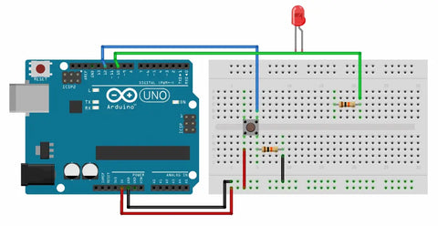
Next you'll need to connect the LED, when using an LED it's important to connect it the correct way around otherwise it won't work and you can damage the LED. It's easy to tell which side is positive and which is negative on an LED as one pin will be longer than the other. The longer pin is the positive side. We'll be connecting this to the same vertical row as the end of the resistor. The last connection we need to make is to connect the negative side of the LED to ground. Using a jumper wire creates a connection between the GND rail and the other pin on the LED, now we have a complete circuit.
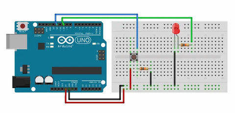
Complete Circuit
Now we've made our two mini circuits, your breadboard should look something like this. Two power connections from the Arduino to the breadboard and two more connections from digital pins, one to each of our sub-circuits. That's all the connections we need to make so we can move onto programming the board.
Creating the program
We've created a new sketch that can be done by selecting a file and then new. In a blank sketch there will be the two main blocks that every program will have. If you're not sure what these are then we'd suggest going back and viewing our first installment in this series.
Let's start by defining which pins we'll be using and how we'll be using them. This is done by using the function pinMode. The function needs to be given two pieces of information. Which pin number we're referring to and how we intend to use it.So for the two pins we're using it would be:
pinMode(12, INPUT); // Input for detecting button press
pinMode(10, OUTPUT); // Output for controlling LED
Next we need to detect the button press and then turn the LED on or off depending on it's status. To do this we'll need to use a variable to store the current value from the button input. There's loads of different variable types but we'll be using one of the most common. A simple integer or INT, this is the primary data-type for number storage. You can create and define variable anywhere in the code but it's best to create them at the beginning of the program to avoid any issues later on. So lets create a variable called button press.
Int button press;
In the main loop of the code the first thing we need to do is read the value at the button input and store it in the variable we jut created. To do this we'll be using the digitalRead function. This reads the value from a specified pin as either HIGH or LOW. Once read we'll be storing the value in the variable we just created.
button press = digitalRead(12); //Stores status of button in variable
The final part of the code is an If ELSE statement with some digital writes. A digital write is similar to a digitalRead except it sets the status of an output pin to HIGH or LOW. It will look at the value stored in the variable. If it meets the condition that we define then it will do something else if it does not meet the condition it will do something else.
This may seem a little complicated but once we type it out i'm sure it'll make more sense. So the first part of an if statement is the condition. We'll be checking if the variable (which is the button status) is high which means the button would be pressed.
if (buttonpress == HIGH)
{
digitalWrite(10, HIGH);
}
Then it's the else part, this is run when the condition is not met. In this case it will be run when the button is not pressed.
else
{
digitalWrite(10, LOW);
}
So the complete Sketch should look like the following:
int buttonpress; //used to store the current value from the button input
void setup() {
// put your setup code here, to run once:
pinMode(12, INPUT); //Input for detecting button press
pinMode(10, OUTPUT); //Output for controlling LED
}
void loop() {
// put your main code here, to run repeatedly:
buttonpress = digitalRead(12); //Store status of button in variable
if (buttonpress == HIGH)
{
digitalWrite(10, HIGH); //Turn the LED on
}
else
{
digitalWrite(10, LOW); //Turn the LED off
}
}
All that's left to do now is program the board and make sure it all works as we are expecting it to! If you're not sure on how to program the board then check out part 1 in this series where we cover that!
Results
Once programmed the LED should be turned off until you press the button down. Then the LED will light up until you remove pressure from the button. For a visual display of what this should look like check the video at the top of this guide.