
In this tutorial, we will be guiding you through the 7th experiment in the Kitronik Inventors Kit. We will guide you through setting up the circuit and coding the program using block programming in the MakeCode software.
Setting Up the Experiment
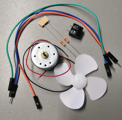
Parts List
- 1x Terminal Connector
- 1 x Motor
- 1x Fan Blade
- 1x M/M Jumper Wire
- 2x M/F Jumper Wire
- 2x 2.2kΩ Resistor (Red, Red, Red, Gold)
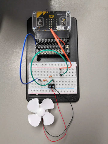
Building the Circuit
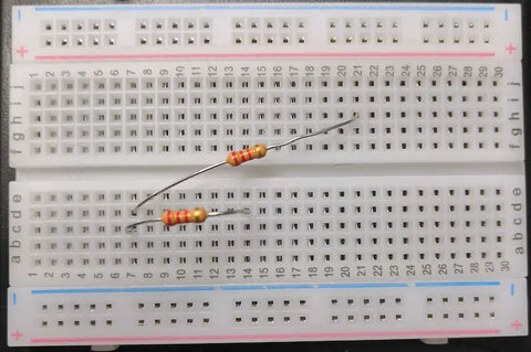
Adding the Resistors
Add the resistors to the breadboard by inserting the pins into the following
- Resistor 1: D7 and H21
- Resistor 2: C7 and D14
Adding the Motor
Place the red (positive) wire on the left-hand side of the terminal connector and the black (negative) wire into the right-hand side. Using a small flat head screwdriver tighten the screws to secure the wires in place.
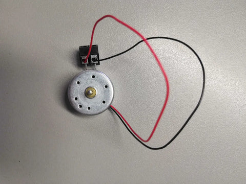
Insert the pins of the terminal connector into holes A14 and A16 on the breadboard. Push the fan blades securely onto the motor.
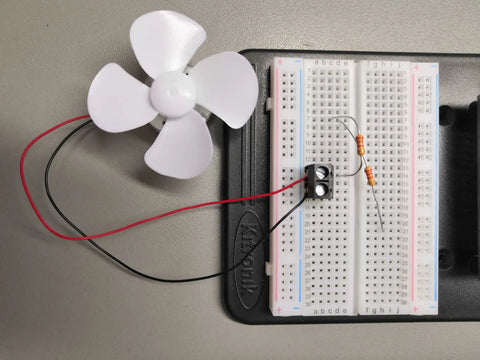
Adding the Jumper Wires
Add the Male to Male jumper wire by inserting the pins into holes E16 and F21
Add the Male to Female jumper wires by inserting the pins into holes
- 0 to E7
- 0V to J21
Coding the Experiment
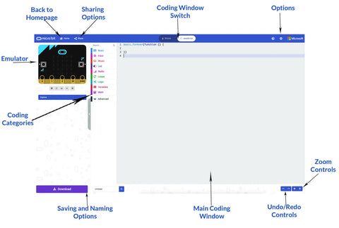
MakeCode Software
Regardless of which OS you are using go to the MakeCode website with any internet browser. The page is broken down into a series of sub-categories with your created projects being at the top along with some premade programs for Tutorials, Games, Radio Games, Fashion and many more!

You can click on any of these to load the code, however, if you wish to start your first or a new project click on the big purple box labelled New Project.

You have 2 coding options within this which can be changed by using the At the top of the page you will notice a slider-style button, click on it to change the coding window to JavaScript mode.
 |
 |
|
Block Mode |
JavaScript Mode |
You should now have a screen that looks similar to this.
Coding Guide
Following the code, the first thing that you need to do is declare 2 variables, these will store numerical values that will be used to gain the voltage value in realtime while the other will store the highest voltage value that has been reached. On lines 1 and 2 type the following code.
let Highest = 0let value = 0You will now need code your forever function and the if statement within it, this means the if statement will be constantly repeated while the program is running. On lines 3 to 8 type the following:
basic.forever(() => {value = pins.analogReadPin(AnalogPin.P0)if (value > Highest) {Highest = value}})Lastly, you’ll need to code the input for when the A button is pressed on the micro:bit that will display the number stored in the variable Highest to the user using the micro:bits LED matrix. On lines 9, 10 and 11 type the following:
input.onButtonPressed(Button.A, () =>{ basic.ShowNumber(Highest)
})Uploading to the Micro:Bit
In the bottom left corner of the MakeCode page, you will find a textbox along with a purple download button. Click on the word untitled in the textbox and give your program a new name.
Press the Download button and the file will download to your downloads folder unless you specified a specific place.

Once the file has downloaded, open up the window for the download location and a separate window for the MICROBIT. Click and drag the file from downloads over to the micro:bit.
Once it has finished, the MICROBIT window will close and reopen, please note that while the file you just copied does not appear in the window, it will have been copied across.