
Welcome to the third episode in our getting started with an Arduino video series. In this edition we will be using a potentiometer to vary the speed of a flashing LED. To achieve this we will need to use some variables, analogue input, digital output and delays in our code in combination with some additional components and the serial monitor in the IDE.
You can use the quicklinks below to jump to the different parts of this post.
- Components List
- Understanding a Potentiometer
- Connecting a Potentiometer
- Reading a Potentiometer Value
- Using the Serial Monitor
- Adding an LED
- Flashing an LED With a Delay
- Results
The components we will be using to create this are:
- Arduino Uno
- Breadboard
- 10K Potentiometer
- LED
- Current limiting resistor (10K)
- Male to Male Jumper Wires
- Male to Female Jumper Wires
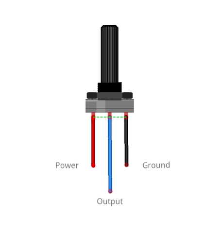
Understanding a Potentiometer
A potentiometer is a great and simple way to create a variable input to a circuit, it's also often also referred to as a variable resistor. It’s a component which you connect to a power supply and ground, then a third connection outputs a voltage that varies depending on the rotation of the potentiometer.
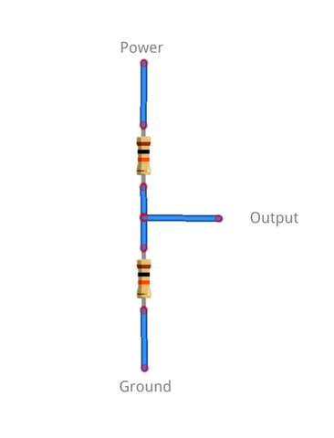
The inside of a Potentiometer acts like a voltage divider circuit, rotating the potentiometer is like changing one of the resistor's values. Changing the resistance also changes the output voltage this is becuase of Ohms Law.
Connecting a Potentiometer
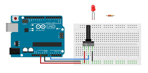
First we’re going to connect the Potentiometer to the Arduino and then look at how the output changes as the knob is turned.
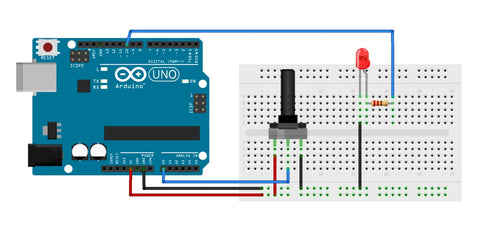
On most potentiometers the outside connections are used for positive power and ground, these are interchangeable and can be used either way around. Connect the female end of the jumper wired to each of the pins on the Potentiometer or plug it directly into the breadboard. Connect the outside pins to 5V and ground. Lastly connect the middle wire to one of the analogue inputs, we’ll be using A0 as the input to the Arduino for our potentiometer.
Reading a Potentiometer Value
Now we’ve connected the potentiometer we need to write a program to read and display the input value. There's a few key parts of the program we need to write. These are the variable definitions, the setup section and the void loop which is where we'll write the code to read the input from the potentiometer.
Code:
int PotentiometerInput = A0;
int PotentiometerValue;
void setup() {
// put your setup code here, to run once:
Serial.begin(9600); //Creates the serial connection
}
void loop() {
// put your main code here, to run repeatedly:
PotentiometerValue = analogRead(PotentiometerInput); //sets variable to value read from pot input
Serial.println(PotentiometerValue); // outputs variable to the serial monitor
}
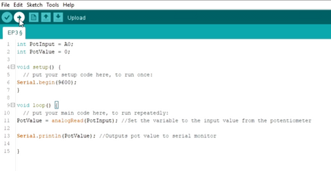
Now we can compile and upload this code to the board.
Using the Serial Monitor
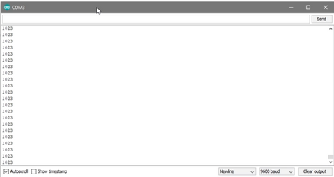
Once it’s done uploading we need to open the Serial Monitor to view the sensors readings. This can be found in Tools -> Serial Monitor. We need to make sure that the baud rate in the serial monitor is the same as in our code. In the serial begin line of code we used the baud rate of 9600.
When you turn the potentiometer all the way to one side the value will be 1023 and 0 on the other side. This is because the Arduino uses a 10-bit analogue to digital converter or ADC to change the analogue voltage produced by the potentiometer into a digital value. It’s a 10-bit convertor which means there are 2^10 or 1024 different values it can be. This is why the inputed reading can be anything between 0 and 1024.
Adding an LED
Now we know how to read an analogue input lets use variable input value to control how fast an LED flashes. Before we can do this we need to connect an LED to the Arduino, we’ll do this in the same way as in the previous blog.
We'll use a jumper wire to connect a digital pin to the current limiting resistor, we’ll be using pin 10. Next connect the positive side of the LED which is the longer leg to the other side of the resistor and lastly connect the other side of the LED to ground.
Now everythings connected lets get onto the code.
Flashing an LED With a Delay
Rather than creating a whole new sketch we’re going to update the one we just created. We need to create some new variables to store the LED pin definition in, remove the serial monitor code and turn the LED on/off with a delay.
Code:
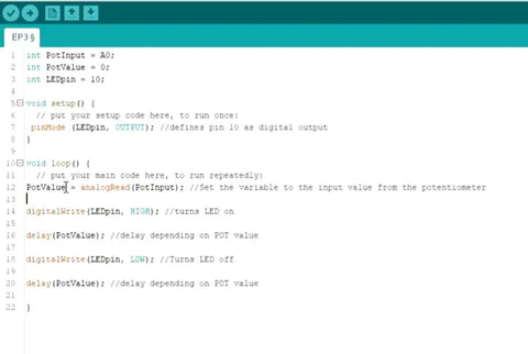
//The following lines define the pins & variables we'll be using
int potPin = 2;
int ledPin = 8;
int potval=0;
void setup() {
pinMode (ledPin, OUTPUT);//Sets the LED pin as an output
}
void loop() {
potval = analogRead(potPin); //reads the analogue voltage from the pot via ADC and stores it in the variable
digitalWrite(ledPin, HIGH); //turn the LED output pin high turning the LED on
delay(potval); //waits an amount of time dependent on the potentiometer position
digitalWrite(ledPin, LOW); //turn the LED output pin low turning the LED off
delay(potval); //waits an amount of time dependent on the potentiometer position
}
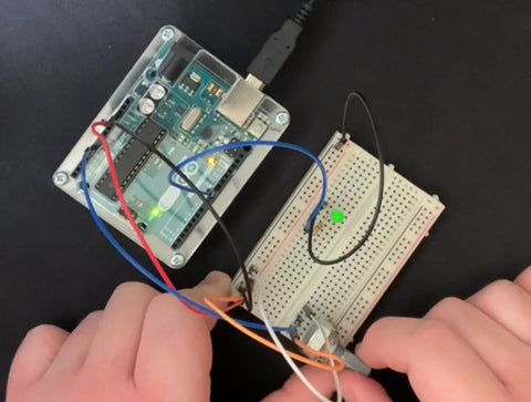
Results:
When programmed with this code the speed at which the LED flashes will depend on the position of the potentiometer. If you turn the pot all the way in one direction then the light will flash extremely slowly, and the LED will be constantly on in the other direction. This is because the LED is flashing faster than your eye can process so it appears as constant light.
This code and circuit could possibly be expanded for use in audio and visual systems. It could be used for volume or brightness control, setting contrast, tone control in audio equalizers and so much more!