Quick Links:
- Parts List
- Legs Assembley
- Main Body Assembley
- Control Boards
- Attaching Legs
- Connecting Servos
- Programming
Parts List:
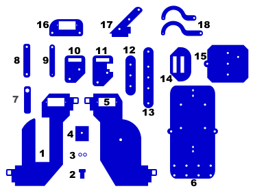
- Main Body Section 1 x 1
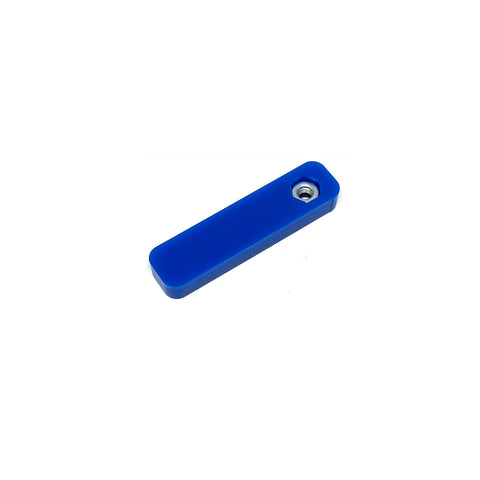
- T-Pegs x 4
- 3mm (x1) & 5mm Spacers (x10)
- Main Body Square x 1
- Main Body Section 2 x 1
- Top Mount (Protoboard, Motor:bit, and Kitronik Compatible)
- M3 Hex Wrench x 1
- Upper Leg Section x 8
- Leg Servo Lever x 4
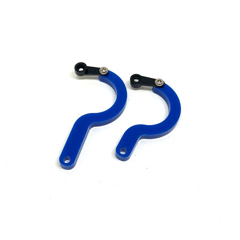
- Hip Type 1 x 2
- Hip Type 2 x 2
- Small Middle Spacer x 1
- Long Middle Spacer x 1
- Foot x 4
- Main Body Lever Mount x 1
- Leg Servo Mount x 4
- Lower Leg x 8
- Main Body Servo Levers x 2
In the box there will also be:
- 6 x Servo Packs
- 1 x Protoboard
- 1 x 9V Battery Holder
- 1 x AA Battery Holder
- 1 x Stick-on Velcro
Screws/Bolts:
- 12 x 16mm
- 14 x 20mm
- 7 x 25mm
- 7 x 30mm
- 40 x Nuts
This includes spares for each size so don’t panic if you have bolts/nuts left over. Depending on batch the screws/bolts could be either flathead or phillips so we’d suggest using a small flathead screwdriver.
Tools Required:
- Small Flathead Screwdriver
Legs:
Assembley x 4
- Start by slotting the two lower leg sections into the foot
- Then take two upper leg segments and place one in between the lower legs lining the screw hole up.
- Then insert a 25mm screw and place the other upper leg segment on the other side ensuring that the screws are inserted from the curved side of the foot.
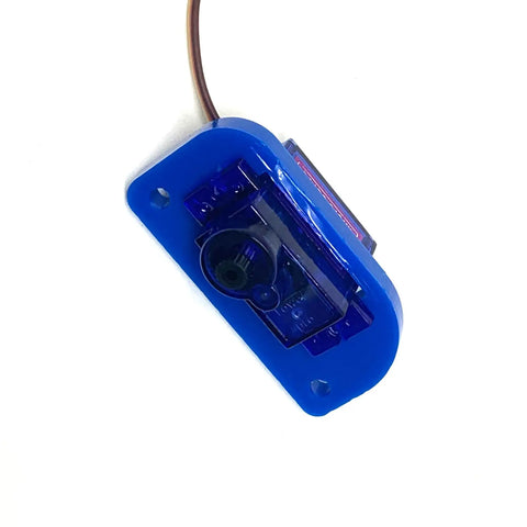
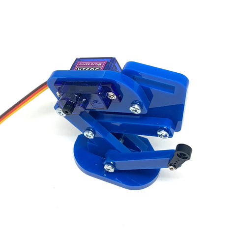
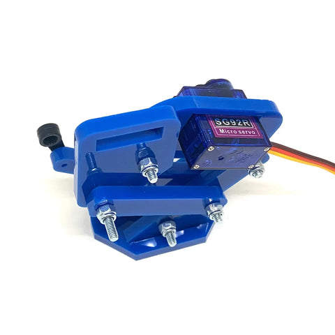
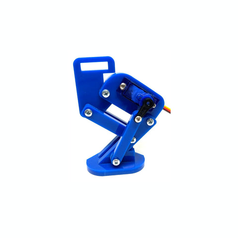
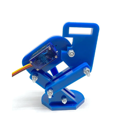
- Insert the Servo into the Upper Leg Servo Holder ensuring that the wire is pointing towards the less curved side. You’ll need to feed to wire through the gap and then slot the servo into place. Then secure it using one of the larger screws from the servo pack
- Connect the Servo Holder to the rest of the leg using the screw hole on the side the wire is. Use a 20mm screw
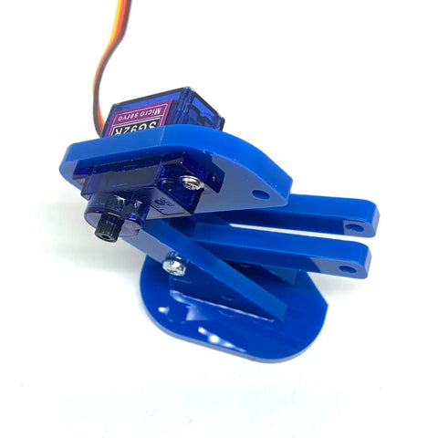
- Now using one of the hip pieces connect the other side of the servo holder to the higher screw hole on the hip ensuring that the servo holder piece is on the outside. Use a 16mm screw.
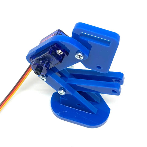
- Now connect the other side of the hip to the upper leg segments we connected to the lower leg earlier. The hip segment should sit between the two other leg segments, and secure it with a nut on the inside of the leg. Use a 20mm bolt for this.
Creating Holes In Servo Horn
We need the servo horn to rotate and move freely with the screw being when attached to the servo lever. If it can not move freely there is too much strain on the servo which can cause damage. For the screw to move freely we need to make a larger hole on the servo horn, we’ve included a self-tapping screw for you to make this whole, alternatively you could use a suitably sized drillbit and drill a hole. Please only do this if you are experienced and under adult supervision.
Creating a hole using the included screw:
- To create and attach the leg lever to the servo and leg you’ll need the remaining large servo screw, single-sided servo horn, a screwdriver and the included self-tapping M4 screw
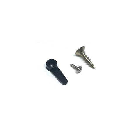
- Start by screwing the self-tapping screw into the second hole in from the end of the horn, only screw the screw in about halfway
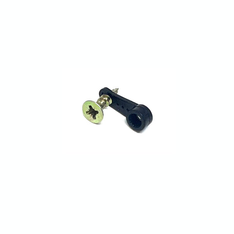
- Now unscrew the screw, flip the horn over and do the same process from the other side
- You should now have a larger hole in which the servo screw can sit inside and rotate freely in
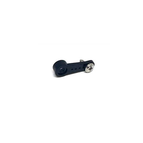
- Now place it over the smaller hole on the leg lever and continue to screw in the screw. Continue to screw until the leg lever is securely held, you do not need to completely screw in the screw.
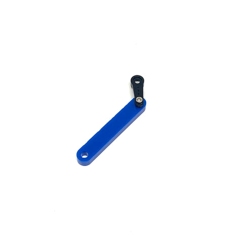
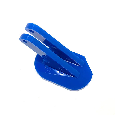
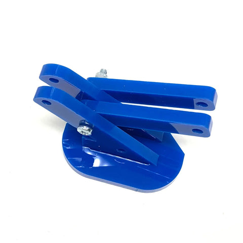
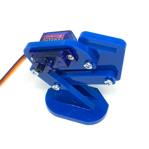
- Now we’re ready to attach the servo lever to the rest of the leg assembly.
- Start by placing a 30mm screw through the lever and then add a 3mm spacer
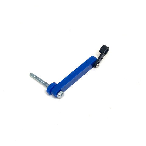
- Then place the screw through the free holes towards the bottom of the legs and secure using a nut as shown in the image below.
- Leave the servo horn unattached from the servo at this point. We’ll connect them after we’ve calibrated the servos.
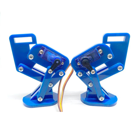
- You’ve now assembled one of the dog's legs.
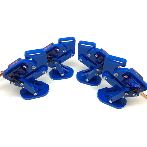
Repeat this another three times making sure to create two left legs and two right legs using one of each hip type on both sides. We’ve just created one leg but the process for creating more legs is the same, just everything is mounted on the other side of the hip.
Once completed your four legs should look like this:
Leg Servo Calibration
Before attaching and securing the servo horns in place we need to change the gear positions to a consistent value. We do this so that when we program the servos we can use similar values to control all the servos while knowing what position the legs are in. These values will need to be fine-tuned when you’re programming but they’re a good place to start.
For BBC micro:bit:
If you’re using the BBC micro:bit and the Motor:bit control board then follow these steps:
Legs:
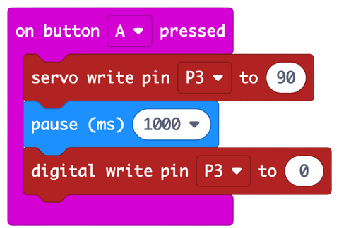
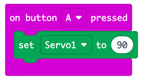
- Upload the code shown below to your BBC micro:bit board
- Insert BBC micro:bit into the Motor:bit
- Connect a servo to the three pins labelled P3 on the Motor:bit ensuring that the servo wire colours match the colours of the pins
- Press the A button to adjust the servo
- Repeat the above steps 3 and 4 for the remaining servos
Code:
The code shown below will move the servo position to 90. The digital write is included in the code to stop the servo from buzzing, it’s optional but we’ve included it.
For Motor:bit Servo Driver:
For Kitronik Servo Driver:
To use the set servo block shown below you’ll need to add the Kitronik I2C Servo Extension. If you’re not sure how to do that please see the Adding a Makecode Extension section.
 Now you’ve adjusted all the servos we can connect the servo horn to the servo finishing the assembly or the legs. The servo's horns fit tightly onto the servo and may need a slight push. Try and connect the horns to the servos in the position shown below. This helps to ensure that all the legs behave in the same way when we’re programming the dog to move.
Once attached you can use the smallest screw included with each servo to secure it in place using the hole in the centre or the servo horn connector.
For Arduino/Other platforms:
We need to attach the servo horns to the servos in a way that ensures all the legs behave in a similar way. To do this we’ll set all the servos to the same value before attaching the horns to them, we’ll use a position value of 90 as it’s in the middle of the servo's range.
The code below sets the servo connected to pin X to position 90. Run this code of each servo before attaching the servo horns.
Code:
#include <Servo.h>
Servo myservo1;//Servo to be tested/calibrated
void setup() {
myservo1.attach(X);
}
void loop() {
myservo1.write(90); //Sets servo position to 90 - the middle of its range
}
Legs:
For the legs, we’d suggest using a position value of 90. This sets the servo’s position to the middle of its range.
Now you’ve adjusted the leg servos we can connect the servo horns to the servos finishing the assembly of the legs. The servo's horns fit tightly onto the servo and may need a slight push. Try and connect the horns to the servos in the position shown below. This helps to ensure that all the legs behave in the same way when we’re programming the dog to move.
Once attached you can use the smallest screw included with each servo to secure it in place.
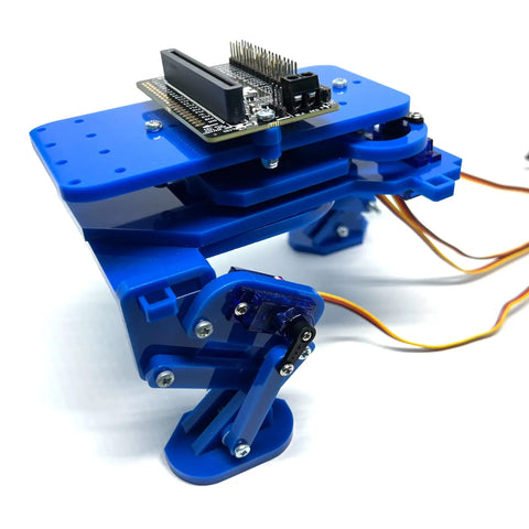
Main Body:
Lever Assembley
First, we need to attach the servo horns (from the two servos remaining) to the levers which move the central body pieces. With both of the curved levers facing to the left attach the servo horns by placing the screw through the hole and screwing it into the small hole on the curved end of the lever.
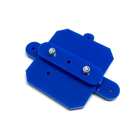
Attach the three pieces shown below together using 2 x 20mm bolts.
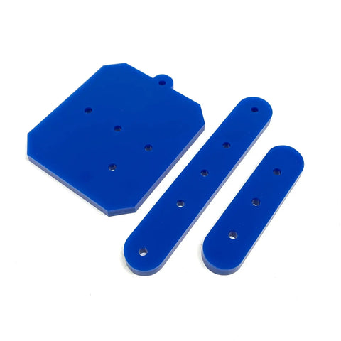 The longer piece and shorter piece are mounted on either side of the square piece.
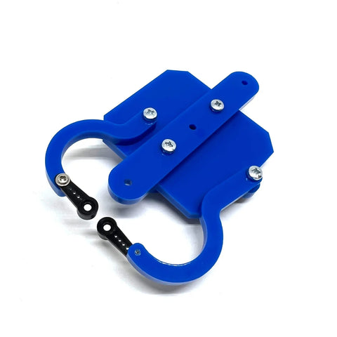
Now using 2 x 16mm bolts and 3mm a 3mm spacer connect the levers to the larger square board as shown in the image below. Ensure the spacer is placed on the bolt and above the lever. The longer lever is connected to the notch on the side of the square and the other to the only other free hole. Ensure both levers curve towards each other.
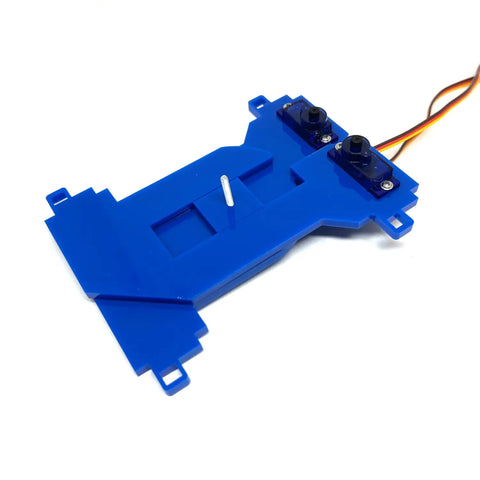
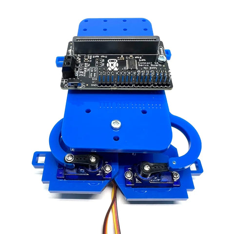
Sliding Body
Place and secure servos in the two sliding body parts as shown below. When placing the servos into the holes ensure that the cog on the servo is nearer the centre of the body piece. Ensure the pieces are orientated as shown in the images below.
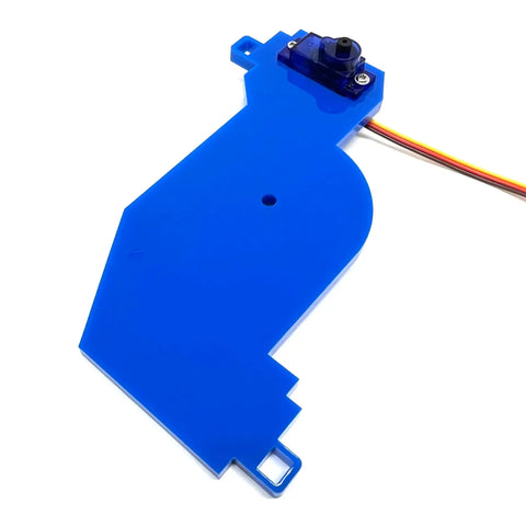 |
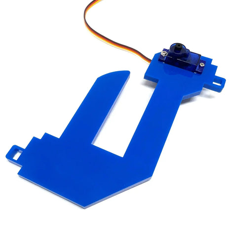 |
Now place the piece with the central slit on top of the other piece and place the square spacer in the central gap using a 30mm bolt to hold it all in a place like shown in the image below.
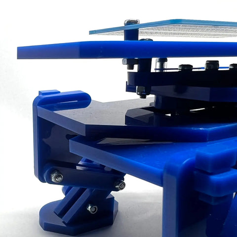
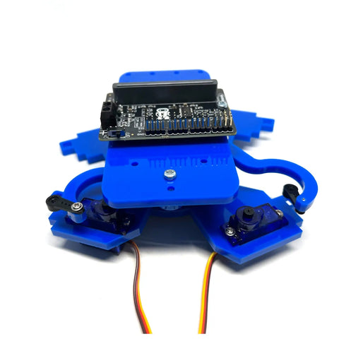
Combining Main Body Pieces
Now we need to combine the main control unit with the lever to the sliding middle section. These need to be secured together tight enough so that the main body is secure/stable and doesn’t wobble but the levers/sliders still have free fluid movement.
To do this you’ll need to line up the bolt from the sliding body section with the central hole on the control board assembly. Once lined upa bolt can be placed through and tightened. 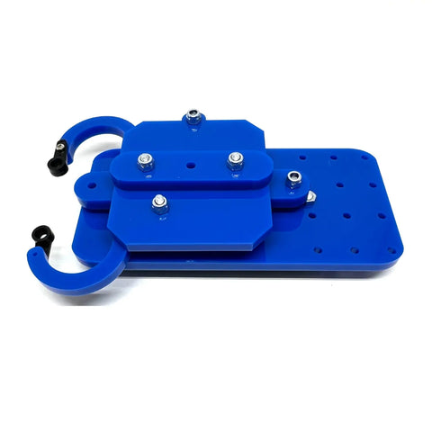
Top Mount Hole Guide
The single top mount that comes with B.E.R.D has been designed so it can be used with a number of different control boards. This means it has a lot of mounting holes, so it's important to use the correct ones.
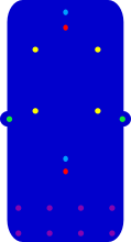
- Green: Kitronik servo board mouting holes
- Yellow: Motor:bit mounting holes
- Red: Protoboard mounting holes
- Light Blue: Middle Spacer mounting holes
- Purple: Expansion holes
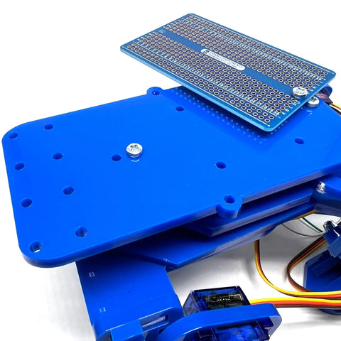
Attaching Control Boards
Protoboard:
Start by connecting the Protoboard to the top mount on the side without the rows of additional mounting holes. Check the Mouting Guide to ensure you use the correct holes. Use a 16mm bolt and 5mm spacer.
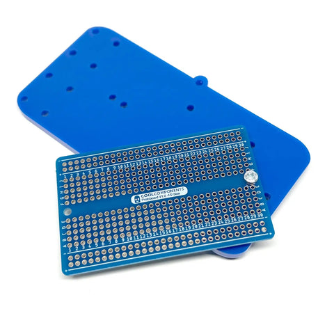 Then connect that same end of the top mount to the main body structure using a 20mm bolt and 5mm spacer between the parts.
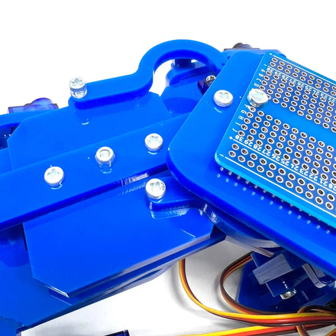
When securing these bolts it can be useful to place the nut inside the wrench then then hold it in place as you screw in the bolt.
Then twist the top mount round and secure it to the other side of the main body using another 20mm bolt and 5mm spacer.
Then lastly secure the other end of the Protoboard to the top mount using another 16mm bolt and 5mm spacer.
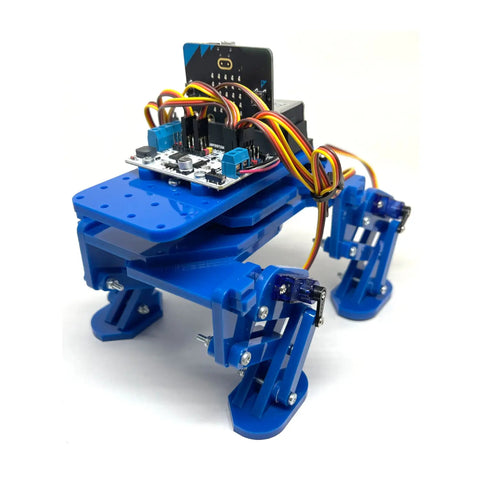
For BBC micro:bit boards:
Start by attaching the Motor:bit or Kitronik Servo Sriver to the top mount using 16mm bolts and 5mm spacers.
Then attach the top mount to the main body, start by attaching the end opposite the mount to the expansion holes to the servo end of the body. Use 20mm bolts with a 5mm spacer between the top mount board and the central mount.
Sliding the main body pieces apart like in the image below can help with access to the hole.
Ensure that the servo levers are facing the servos before securing. Then attach the other end of the top mount using a 20mm bolt and 5mm spacer. At this point the top mount should rotate allowing you to line up the holes.
Make sure not to over-tighten the nut as the body pieces need to slide/rotate freely.
Now we can calibrate and connect the servo levers/horns to the servos for the main body servos.
Calibrating Main Body Servos
Adjusting/calibraing the main body servos is done in the same way as the legs and uses the same code. The only change we’ll make is to the servo values being programmed.
Wth the dog infront of you in the same orientation as the image below, the values we’ll be using are:
- Light servo - Use position value 90
- Right servo - Use position value 180
Program the servos using the same code as you did when setting up the legsusing the above values and them connect the servo horns at a similar angle shown in the image below. Once attached you can use the smallest screw included with each servo to secure it in place using the hole in the centre or the servo horn connector.
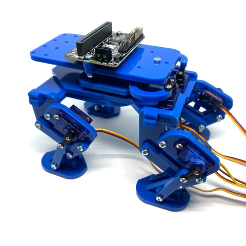
Attaching Legs:
When we built the legs we build 4 different configurations. Two of the legs are for one side of the dog and the other two, for the other side. They can easily be recognised by which side of the hip section the servo is mounted.
On each side of the dog, there is a front leg and a back leg. The front leg uses a different hip piece than the back leg and is attached to the end which has the main body servos. It has a section cut out of it to allow the leg to rotate.
Identify the front and back legs for each side.
We’ll attach the front leg on one side and the back leg on the other side. This will help to balance the dog as we’re attaching the legs. The bend in the leg should point towards the middle/body servos as shown in the image below.
Attach two legs that are diagonally opposite to each other and secure them in place by gently inserting the T-pegs.
Repeat the process for the other two legs and then the dog is assembled!
Connecting Servos:
BBC micro:bit:
You can in theory connect any of the servos to any of the pins available on the control board but we’ll detail the connections we’ve made below. These will be the pin assignments we’ve tested and referred to in our example code. If you decide to connect the servos up differently remember you’ll need to alter the example code as well.
Please Note: When using the Motor:bit servo board It’s important that you use the blue connectors for the legs of the dog as these are all 5V connectors which means the servos will perform better under load.
Place the assembled dog in front of you with the middle servos closest to you and the additional mounting holes furthest away.
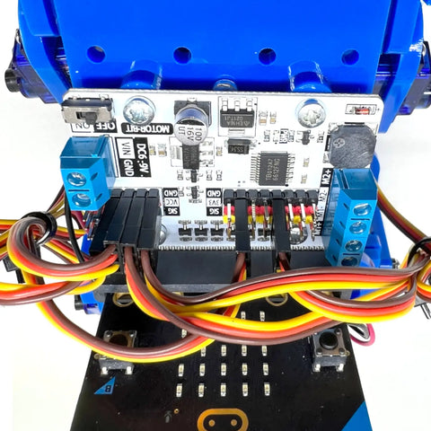
Now when looking down at the dog we have a top, bottom, middle and a left, and right we can start connecting the servos up to the control board.
Top Left: 14
Top Right: 16
Bottom Left: 13
Bottom Right: 15
Middle Left: 6
Middle Right: 10
For Arduino/Other Platforms:
You can in theory connect any of the servos to any of the pins available on your microcontroller but we’ll detail the connections we’ve made below. These will be the pin assignments we’ve tested and referred to in our example code. If you decide to connect the servos up differently remember you’ll need to alter the example code to reflect the used pin assignments.
Using A Battery Holder
The B.E.R.D kit includes two battery holders which provide different power options, you can also power your control board/circuit with a different power supply if wanted. The 9V battery holder can be used with the Motor:bit and the AA battery holder can be used with Kitronik Servo Driver or other Arduino boards.
To attach the battery holders to the dog peel of both sides of the Velcro and attach one to the back of the battery holder and the other to the position on the dog you'd like to place the battery holder.
We'd advise placing the battery pack as central as possible on the underside, placing it to far off center can place too much weight on the servos and damage/break them.
Programming
Now you've built B.E.R.D it's time to get moving, we've put together some programming and code example for both the BBC micro:bit and Arduino platforms. Use the links below to go to the guide for your platform: