LEDs are one of the most popular components, they can be used for a range of things from displays to troubleshooting tools. But how do you use and connect them to an Arduino based development board? Before we connect an LED to an Arduino we frst need to understand how an LED works.
Standard LED Circuit
Below is an example of a simple LED circuit that would light up most standard LEDs. It's composed of an LED, current limiting resistor and a AA battery all connected in series.
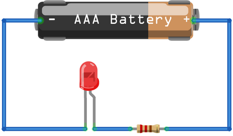
Each LED consists of an Anode (positive) and a Cathode (negative) connections and it's important to connect an LED up the correct way to ensure you don't damage it when current flows in the wrong direction. It's fairly easy to determine which side is positive and negative, the longer or leg with a notch in it is the Anode (+) and the other leg is the Cathode (-). The LED also needs a current limiting resistor, this will ensure that the LED is protected from overcurrents which would damage and break it.
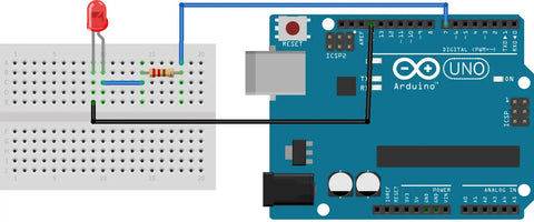
Standard Through-Hole LED
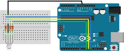
Now we know how an LED is powered and used in a normal circuit let's alter the circuit above slightly so it's powered via the Arduino.When using the Arduino we'll be using a digital pin (pin 7) to control positive power to the LED and the boards designated ground pin. Like before we'll need to use a current limiting resistor to protect the LED.
Programming the Arduino
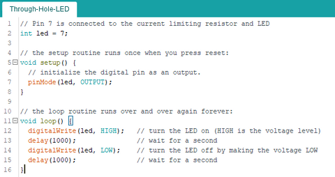
To progam the board we'll be using a modified version of the Blink example that's built into the Arduino IDE. There are three main parts of the code, creating a variable, defining the pin and then lighting the LED.
Creating a variable for the LED pin is done outside and before the void setup or viod loop sections. Next we need to declare the pin we're using and how it will be used, this is done inside the void setup section of code. We'll be using pin 7 as an output, as we've used a variable to store the LED pin you can use this.
Lastly we need to turn the LED on and off, as the LED is connected to the Arduino output pin we can use a simple digital write to set the output high or low.
You can view the full code below:
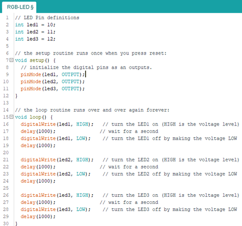
Common Cathode RGB LED
This is an RGB Common Cathode LED, it's three individual LEDs (Red, Green, Blue) with a common ground in a single housing. You use it in the same way as a standard LED, apply a positive voltage to the Anode(+) and ground to the GND pin and it'll light up. This type of LED allows you to create a wide range of RGB colours by mixing which onea are lit and varying the intensity of the individual (R,G,B) LEDs.
When wiring an LED like this it's best to think of it as 3 individual LEDs that share the same ground. Each LED will still need a current limiting resistor and a positive power connection from an Arduino pin.
Programming the board
Programming the board is very similar to the previous example exept this time we have three LEDs to turn on and off. The code shown in full below is the same as the example above just expanded for the other LEDs. When programmed it will light each of the LEDs (R, G, B,) on and off in turn.