
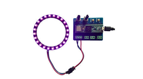
Our new Teensy LED Controller is designed to make using NeoPixel and DotStar LED strips and rings as easy as possible with a Teensy board. The screw terminal connectors mean you don't need to fuss with connectors, simply strip the wires and screw them into place. We've tested it with our range of LED Strips, Rings & Matrixes but it'll work with any LEDs that are compatible with Arduino and use the same connections.
Controller Overview
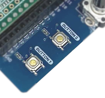
Buttons:
Located on towards the bottom of the board are two pushbuttons labelled BTN1 and BTN2. When Teensy is connected to the board these are connected to P2 and P3 respectivley. When the button is pressed 5V will be present at the data pin, the data pin will be connected to GND. These buttons are perfect for changing between patterns or turning the LEDs on/off.
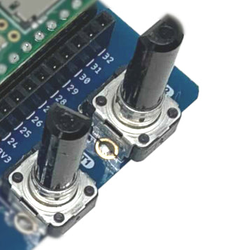
Potentiometers:
On the same edge of the board are two potentiometers with plastic knobs pre-attched, POT1 and POT2. These are connected to analogue pins A10 (P24) and A11(P25).
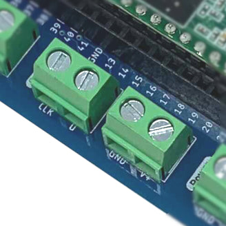
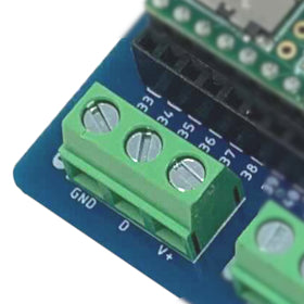
DotStar Connections:
Connect your DotStar compatible LED strips, ring and matrices to these terminal connectors. There are four labelled connections DIN, CLK, V+ and GND. DIN is connected to P4, CLK is connected to P5 and GND is connected to the microcontrollers ground.
NeoPixel Connections:
This connector is for use with all NeoPixel compatible LED devices. It has three labelled connections, DIN, V+ and GND. DIN is connected to P6 and GND is connected to the microcontrollers ground.
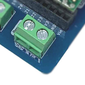
External Power Connections:
This connector is used to connect external power supplys for powering the system. It's connected directly the the Vin pin on the Teensy so is only suitable for power supplies that meet the Teensys requirements of 3.3V-5.5V. Most LED strips run at 5V so you'll need to use a 5V power supply.
Example Code
We've created some simple example code to demonstrate how the various inputs on the LED Shield can be used. You can download the Arduino INO file here, the code is based on Adafruit's buttoncycle example uses the Adafruit NeoPixel library so you'll need to ensure you have that installed for the code to work as expected.
The code uses a button as an input to cycle through LED colours and one of the potentiometers to control the brighness of the LED patterns. The comments in the code below should help to illustrate how it works and what is happening.
 #include Adafruit_NeoPixel.h

#define BUTTON_PIN 2
#define PIXEL_PIN 22 // Digital IO pin connected to the NeoPixels.
#define PIXEL_COUNT 24 // Number of NeoPixels

int BRIGHTVAL = 0; // Variable to store birghness value in
const int POT1 = A10; // Analogue input for Potentiometer 1 on the shield
int Pot1Value = 0; // value read from the pot

// Declare our NeoPixel strip object:
Adafruit_NeoPixel strip(PIXEL_COUNT, PIXEL_PIN, NEO_GRB + NEO_KHZ800);
// Argument 1 = Number of pixels in NeoPixel strip
// Argument 2 = Arduino pin number (most are valid)
// Argument 3 = Pixel type flags, add together as needed:
// NEO_KHZ800 800 KHz bitstream (most NeoPixel products w/WS2812 LEDs)
// NEO_KHZ400 400 KHz (classic 'v1' (not v2) FLORA pixels, WS2811 drivers)
// NEO_GRB Pixels are wired for GRB bitstream (most NeoPixel products)
// NEO_RGB Pixels are wired for RGB bitstream (v1 FLORA pixels, not v2)
// NEO_RGBW Pixels are wired for RGBW bitstream (NeoPixel RGBW products)

boolean oldState = HIGH;
int mode = 0; // Currently-active animation mode, 0-9

void setup() {
 pinMode(BUTTON_PIN, INPUT_PULLUP);
 strip.begin(); // Initialize NeoPixel strip object (REQUIRED)
 strip.show(); // Initialize all pixels to 'off'
}

void loop() {
 // Get current button state.
 Pot1Value = analogRead(POT1); //Stores input potentiometer value in variable
 BRIGHTVAL = map(Pot1Value, 0, 1023, 0, 255); //Changes input into value between 0 & 255
 boolean newState = digitalRead(BUTTON_PIN);

 // Check if state changed from high to low (button press).
 if((newState == LOW) && (oldState == HIGH)) {
 // Short delay to debounce button.
 delay(20);
 // Check if button is still low after debounce.
 newState = digitalRead(BUTTON_PIN);
 if(newState == LOW) { // Yes, still low
 if(++mode > 8) mode = 0; // Advance to next mode, wrap around after #8
 switch(mode) {           // Start the new animation...
        case 0:
          colorWipe(strip.Color(  0,   0,   0), 50);    // Black/off
          break;
        case 1:
          colorWipe(strip.Color(255,   0,   0), 50);    // Red
          break;
        case 2:
          colorWipe(strip.Color(  0, 255,   0), 50);    // Green
          break;
        case 3:
          colorWipe(strip.Color(  0,   0, 255), 50);    // Blue
          break;
        case 4:
          colorWipe(strip.Color(  252,   240, 3), 50);    // Yellow
          break;
        case 5:
          colorWipe(strip.Color(  152,   3, 252), 50);    // Purple
          break;
        case 6:
          colorWipe(strip.Color(  252,   3, 219), 50);    // Pink
          break;
      }
    }
  }

  // Set the last-read button state to the old state.
  oldState = newState;
}

void colorWipe(uint32_t color, int wait) {
 for(int i=0; i<strip.numPixels(); i++) { // For each pixel in strip...
 strip.setPixelColor(i, color); // Set pixel's color (in RAM)
 strip.setBrightness(BRIGHTVAL); // Set brightness value between 0-255
 strip.show(); // Update strip to match
 delay(wait); // Pause for a moment
 }
}